1. Intro
Why this project? I wanna build a robot from scratch to fill the gap between theory and reality.
To build the robot, usually need following knowledge base
- Mechanics, the build the body of robot
- Electronic, the power of the robot
- Computer, the brain of the robot
2. Goal
For the robot, I would like to focus on the mobile robot platform
Two level goals:
- Basic level, the robot can move, and use the lidar as a SLAM sensor, can track something using camera
- More precise control, going from A to B, the error should be less than 1cm
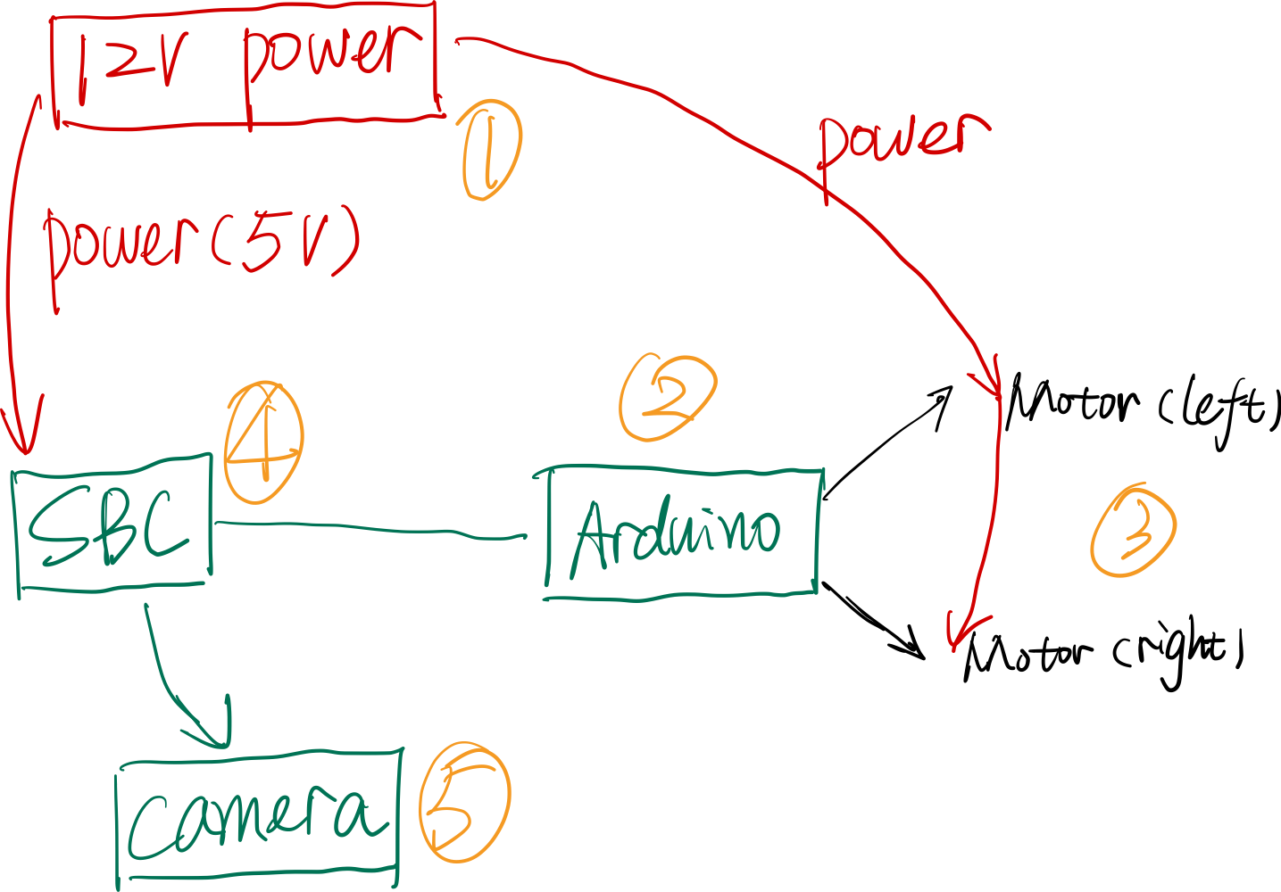
Consider a layer platform
- Environment sensing, different sensor to be used, a SBC is used. LiDAR, video camera, speaker, microphone
- Intelligence, communication, SBC, control other part
- Navigation, get the high-level command and go to desired position
Communication Ethernet
3. Path
Motor
- Control how it works
- feedback control
- position control
- speed control
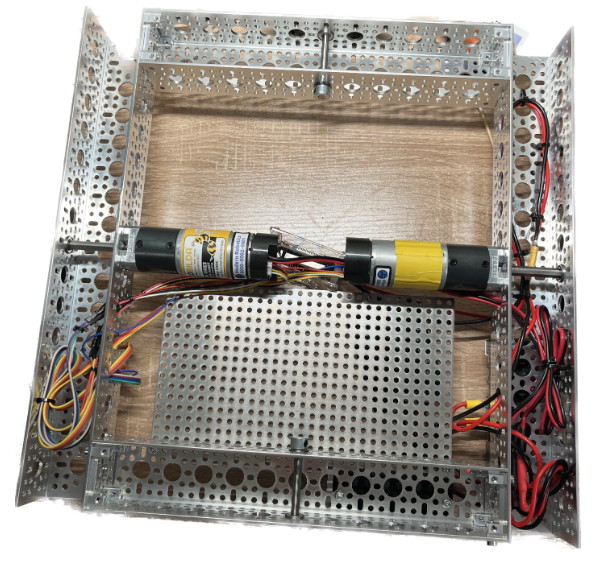
4. Chassis
Design
34cm 30cm 23cm
Front x2
Rear x2
5. New Thing
5.1. Motor Driver
Working with DC motor
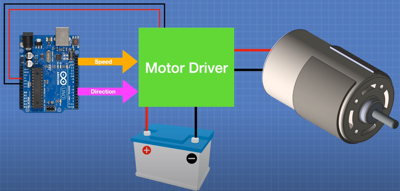
- Direction
- Using the H-bridge could change the direction of voltage and current
- MOSFET would drop a little voltage
- Speed
- PWM
L298N, simple, classic but too old
More improved design:
- TB6612FNG, improved version of L298N
- DRV8871, if you only need a SINGLE motor to drive
- MX1508, small, but not soldering friendly
Driver that can handle large current:
- DBH-12,20A, peak 30A
- IBT2, single channel, 30A, peak 43A
5.2. Micro Controller
UNO or raspberry pi PICO
Pico should be a better choice in 2022 (introduced in 2021)
- Much faster (133MHz vs 16MHz)
- Much larger RAM
- Lower power DC (1.8v-5.5v)
- More port (Analog and Digital)
5.3. Battery
LIPO battery, high capacity in lightweight
Con: easily damaged
Lithium-Ion Polymer (锂离子聚合物电池)
- Application where weight matters
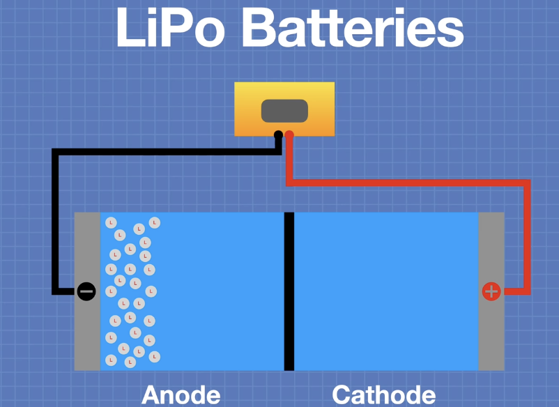
Each cell can provide 3.7V
- Fully charged 4.4V
- Minimum safe charge is 3.0V
Different wire
- S- serial
- P- Parallel
Capacity
- C rating
Connection:
- Dean
- XT60
- EC3
5.4. Base Material
Consider: strength to weight
Aluminum
- lightweight
Acrylic (亚克力)
- lightweight
- drilled
5.5. Channeling System
Actobotics system: good availablity
GoBilda system: good quality, successor to the Actobotics
Vex system
Lynxmotion
5.6. Motor Selection
DC Gear motor
- Planetary: a bit expensive, but quiet
- Spur: cheap, but noise
Things to consider
Nominal voltage, optimal voltage
No Load RPM, when nothing connected, what is the RPM
Stall torque and current. Newton Meter
Stall: no more move
<30% stall point
Size and shaft
Mount
Shaft may not in the center
Encoder is important
We need to first determine the
- Weight (Load)
- Speed
- Longest working area for the robot
- The robot should be slower than human walking (safe to control the robot)
Calculate the required specification for the motor and battery
Motor, hub, bearing, encoder
- Bearing is quite important since the whole load is on the wheel
- if there are no bearings, the motor would load all the pressure
5.7. Wheel
Parameter for wheel:
- Wheel size, determine the speed
- Wheel width, determine the traction and maximum load
- Wheel traction, determine the surface robot can travel
- Wheel type, determine the degree of movement
Type
- Standard, most common, wide range size, can be used as driver or idler
- two degree (forward and backward)
- Caster and Ball wheel, orientable, use as idler, most used for indoor design
- Mecanum, different left and right wheels, multi-drirectional, 45 degree roller
- Omni wheels, 90 degree roller, 4 degree of freedom, best for indoor
Arrangement
Durometer
- harder or softer?
- 30A maybe too soft
5.8. Electronics
Motor driving
Power distribution board
Motor controller
Fuses: (保险丝)
- if the current is too big, would case heat, may lead fire

5.9. Power Source
Regulator and Convertor
Logic voltage, 5V(4.7-5.2), 3.3V.
Motor: 6V, 12V
AC:
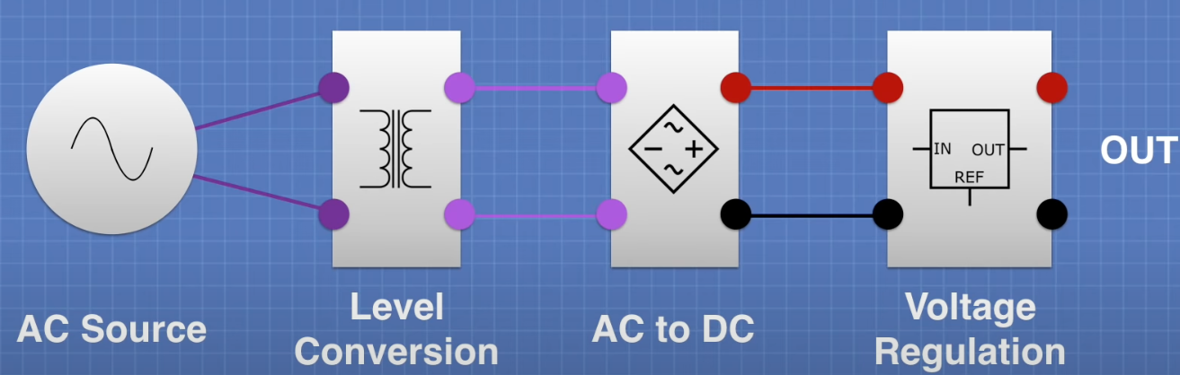
DC:
- From high to low:
- voltage regulation,AMS1117-5(much lower voltage drop), 1A
- buck converter, high-efficient, mini360
- From low to high
- boost converter, PSM205, to a usb
- From any to any
- Buck boost converter, S9V11F5 (from 2-16 to 5)
5.10. Motor Controller
5.11. Weight Consideration
If the robot is too lightweight, there would be not enough traction for the robot to move.
5.12. Connector
JST
6. BOM
| Part | Name | Num | Check |
|---|---|---|---|
| Front wheel | Motor | 2 | 1 |
| Front wheel | 120mm Wheel | 2 | 1 |
| Front wheel | 8mm REX bearing | 2 | 1 |
| Front wheel | 8mm Face bearing | 2 | 1 |
| Front wheel | 8mm shim | 4 | 1 |
| Front wheel | m4 washer | 8 | 1 |
| Front wheel | Hyper Hub | 2 | 1 |
| Front wheel | 12mm M4 screw | 8 | 1 |
| Front wheel | 18mm M4 screw | 8 | 1 |
6.1. Omni wheel
| Name | Num | Check |
|---|---|---|
| Omni wheels | 4 | 1 |
| Spacer 4mm | 2 | 1 |
| 6mm D shaft hub | 2 | 1 |
| 6mm D shaft bearing | 4 | 1 |
| 6mm Collar | 2 | 1 |
| 30mm M4 screw | 8 | 1 |
| 80mm 6mm D-shaft | 2 | 1 |
7. Progress
11.21
12.5 Test Robot Motor
- Full Speed
- Arduino PWM
- 20%
- 50%
- 100%
- Encoder
- Each rotation
TODO:
- Add a ferrule crimping tool kit
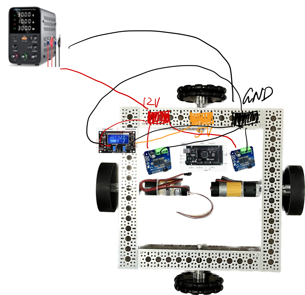
Motor Driver:
VCC is connected to 5V power supply of MCU,GND is connected to GND of MCU.
R_EN AND L_EN short circuit and input PWM signal for speed regulation
L_PWM,pin input 5V level,motor forward
R_PWM,pin input 5V level,motor reversal
1 | void setup() { |
7.1. Update Dec.10
Currently the robot works great on open-loop rotate and move forward, backward
Next
- Close-loop control on the RPM
Test how linear the motor is. That is the relation between the PWM duty rate and the RPM
7.2. Update Dec.13
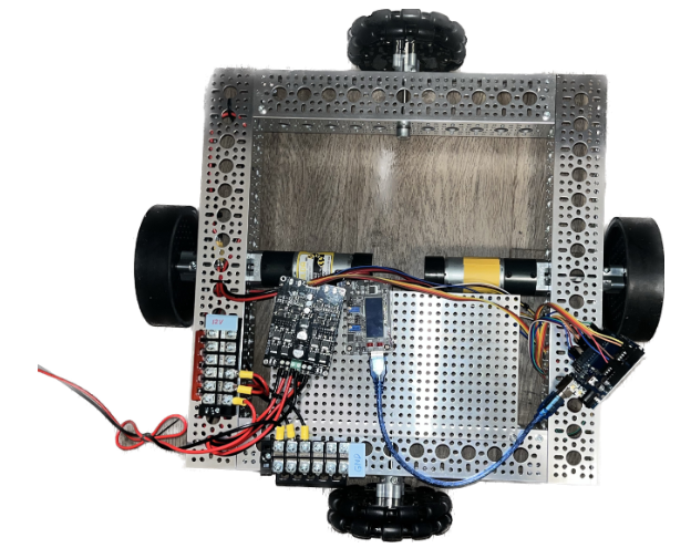
Re-organize the wire and hide the wire in the alumni channel
Currently the robot’s speed control is under PID control
To make the position control closed-loop, still need encoder+IMU
And localization system should be added (SLAM)
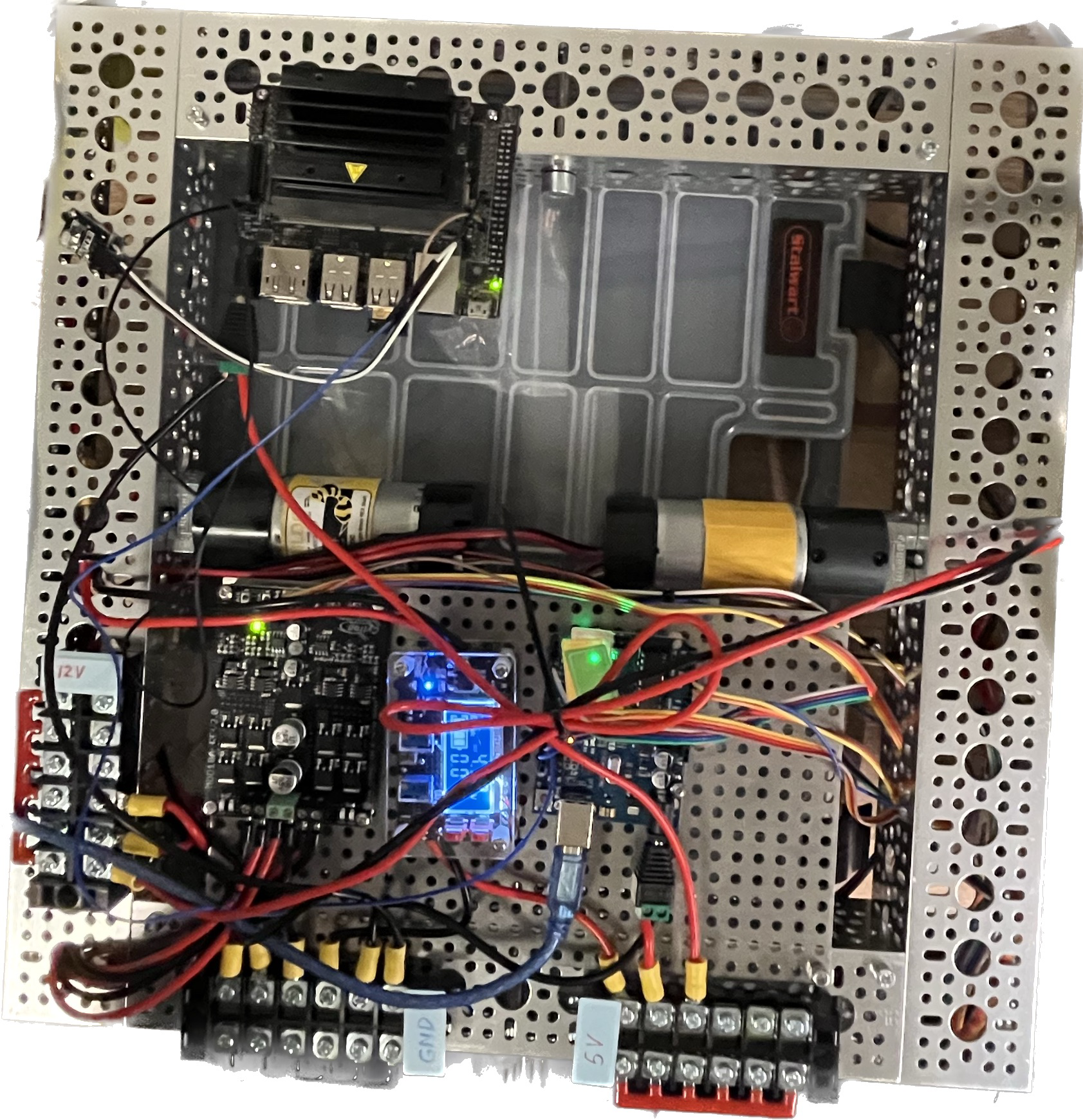
7.3. Update Dec.15
Use DC jack to power the Jetson and Arduino
Given the hardware and electronic elements I have, followed step
Arduino Remote ControlJetson useCommunicate with computerSetup wifi enable remote accessRead IMU dataInstall Lidar and read lidar data
7.4. Update Dec.17
Rewire the arduinoPower Arduino with Jetson NanoCommunicate between arduino and jetson nano
7.5. Update Dec.19
Add IR remote in arduino
TODO:
Remote control move forward/reverse/rotate- Use the lidar to build the map
7.6. Update Dec.21
Remote speed control and stop done
TODO:
- Add IMU
WireRead dataCalibrateStore offsetReload offset- 3D print a level for lidar
- SLAM
8. Takeout
Low frequency PWM would cause the motor hauling, by increasing the frequency (like 3k) the hauling would disappear. In some MCU, by playing with the register, we might change the default frequency.
While selecting the MCU, checkout how many interrupt are needed and how many interrupt can the MCU provide.
By using encoder’s both channel and both rising and falling, we can maximize the accuracy of the motor
A good motor is almost linear between RPM and PWM
When the code doesn’t go well, check the setting and setup
After rewiring, double check the position especially the pin number
While making the wire, the length or wire should be considered. It’s a system design, so leave some room for wiring but not too much