1. What
For a IMU, it can measure
- linear acceleration
- angular velocity
What to calibrate:
- measurement bias
- constant over time, independent of sonsor motion
- due to manufacturing tolerance
- scale factor
- constant over time
- due to tolerance
- misalignments
- drift rate
- Noise
2. Basic Math
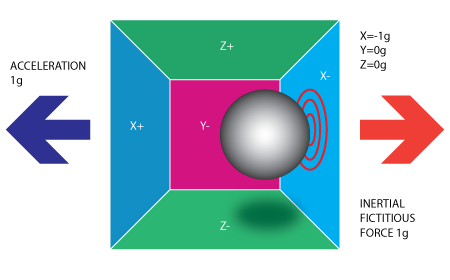
How accelerator works: MEMS

The basic is: detect force
Calculation:
- get 3 (xyz) axis voltage $\to$ ADC to digital signal (in a range) $\to$ convert into real acc, $(V_x-V_{x_0})/Sensitivity$
3. Calibration
What to Calibrate?
- Scaling
- Misalignment
- Bias
Process:
- In a static position, the norms is equal to the gravity + a error factor
- After calibration of accelerometer, we use it as reference
- Intergrating the angular velocity and compare with the pose calculated by accelerometer
Notes:
require a larger number of static states
model the gyroscope bias drift using Allan variance
Definition: $\sigma_y^2(\tau)=\frac{1}{2}<\left[y_{i+1}(\tau)-y_i(\tau)\right]^2>$
can be used to analyze angular random walk, rate random walk, bias instablity
exploit sampling window, cutting thersh that automatically estimated in the framework
Use Runge-Kutta numerical integration to improve the accuracy of the gyro calibration
A method of numerically integrating ordinary differential equations by using a trial step at the midpoint of an interval to cancel out lower-order error terms. The second-order formula is
$$
\begin{aligned}
k_1 & =h f\left(x_n, y_n\right) \
k_2 & =h f\left(x_n+\frac{1}{2} h, y_n+\frac{1}{2} k_1\right) \
y_{n+1} & =y_n+k_2+O\left(h^3\right)
\end{aligned}
$$
For RK4
$$
\begin{aligned}
k_1 & =h f\left(x_n, y_n\right) \
k_2 & =h f\left(x_n+\frac{1}{2} h, y_n+\frac{1}{2} k_1\right) \
k_3 & =h f\left(x_n+\frac{1}{2} h, y_n+\frac{1}{2} k_2\right) \
k_4 & =h f\left(x_n+h, y_n+k_3\right) \
y_{n+1} & =y_n+\frac{1}{6} k_1+\frac{1}{3} k_2+\frac{1}{3} k_3+\frac{1}{6} k_4+O\left(h^5\right)
\end{aligned}
$$