1. Method
- Identity the behavior of the object to be controlled.
- In theory, analyze the response, the more linear, the easier to control
- Design Controller
- Check the result and tune
2. Behavior
Collect the data by giving the motor PWM from 0 to 255, record the RPM and see whats going on
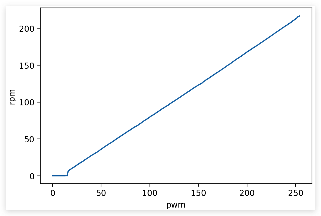
We can see that the relation is almost linear
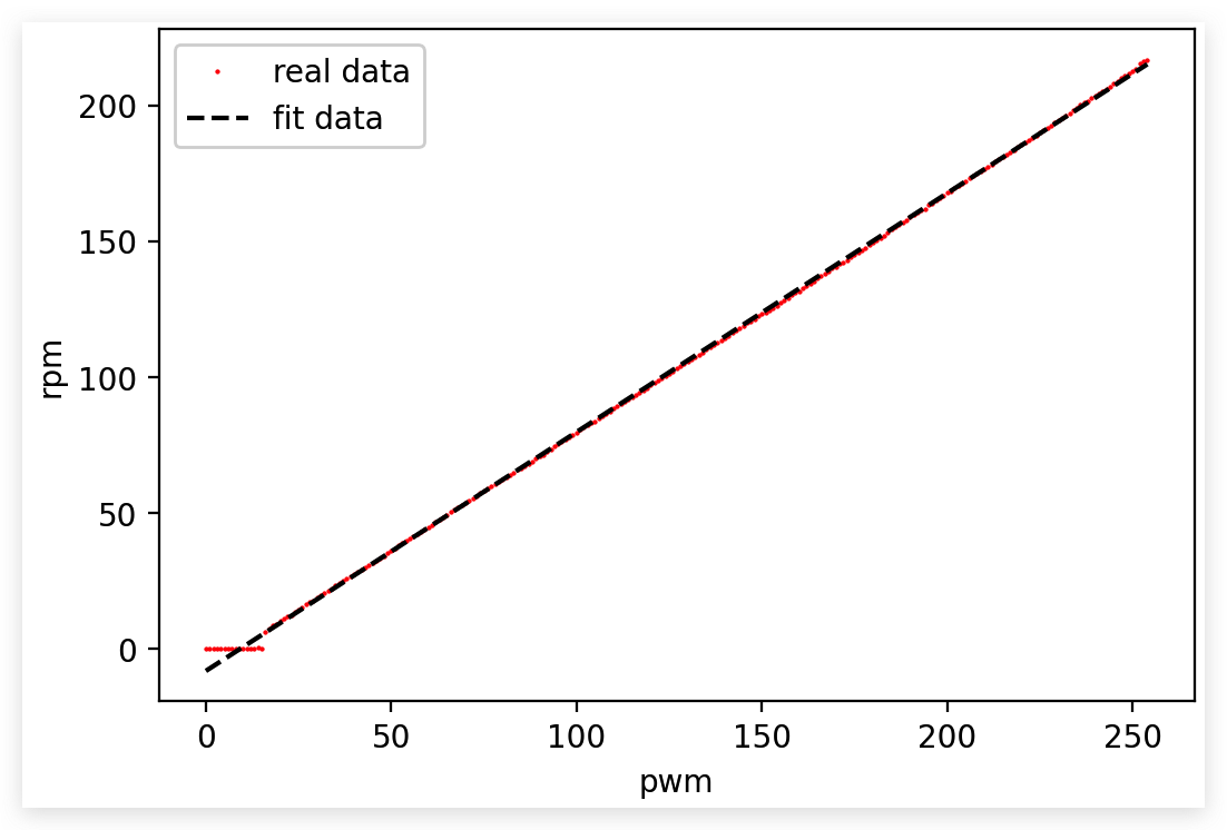
So we can fit the data
$$
RPM=0.88PWM-8.1
$$
Above is the data from right motor, things in left motor is similar
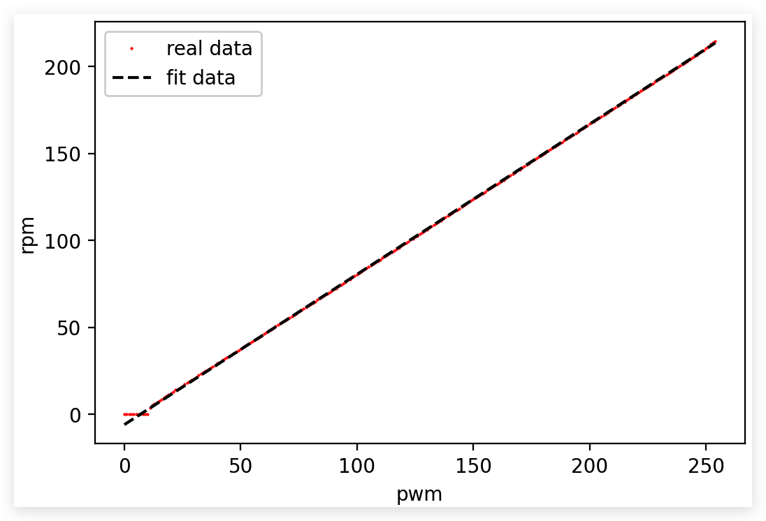
However, the coef is a little different
$$
RPM=0.86PWM-5.99
$$
Maybe two reason
- Error introduced while manufacturing the two motor
- Error while installing the two motor
2.1. Response Time
We need to see how quickly the encoder can calculate a accurate RPM
How much pulse the system need? We need to be accurate in slowest situation
From the data, the RPM start to be normal from 10 RPM while given PWM around 20.
Let’s see 10RPM, means 10/60 per seconds, times 187, around 30 pulse, not enough, if we use both RISING and FALLING signal and use two signal, it would be around 120 pulse in a second, then 200ms (24 count) would be enough.
Conclusion: 200ms (4% error max), 100ms (10% error max)
Use 100ms
2.2. PID
- Add fraction, the RPM should be smaller
- We need to increase PWM to maintain the desired RPM
Say the working speed at 0.2m/s
$$
v=2\pi \times r\times\frac{RPM}{60}\
RPM=\frac{60v}{2\pi \times r}
$$
The $r$ here is 0.06m, so RPM should be $\frac{60\times 0.2}{2*\times 3.14\times 0.06}=31.8$
Let’s see how much PWM we should give to motor?
- For right motor,(31.8+8.1)/0.88=45
- For left motor, (31.8+5.99)/0.86=44
Be generous, just use the 45
In the experiments, we can see that while the PWM is 45, the RPM should be around 33 without load.
By giving a fraction (holding a book on the wheel), the RPM is 23